HOME
SOFTWARE
--- CFDStudio
--- ANSWER
Applications
Examples
ANSWER Express
Publications
Users
Price List
Request Demo
ANSWER Tutorials
ANSWER Manual
--- PORFLOW
--- TIDAL
--- RADM
--- TOOLS
DOWNLOADS
APPLICATIONS
CONSULTING
STORE
COMPANY
CONTACT
FAQ
 

ACRi -- Analytic & Computational Research, Inc.


1 2 3 4 5 6 7

FLOW PAST TWO SQUARE CYLINDERS

Before You Start:This Tutorial Problem Requires ANSWER™ v5.5. The users of the software are encouraged to walk through this tutorial and reproduce it on their own while following, rather than just browsing through it.

The flow past a pair of square cylinder kept in a channel can be chosen as a simple CFD problem for the beginners.

In this tutorial, we will set up a 2D grid and solve the flow using ANSWER™ v5.5.

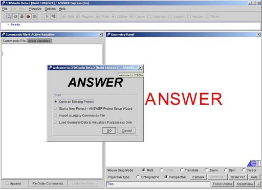
1) Launch ANSWER™. The opening screen of ANSWER™ v5.5 looks like as in Fig.1.1.

Fig - 1.1: Opening screen for ANSWER™ v5.5. Wizard

This is basically frame window with menu bar, tool bar and status bar at the top followed by command window in the left and geometry window in the right. The top bar provides the navigational menus, and has the look & feel of a generic windows menu bar. The left frame is the home of the command file and a list of active variables for the problem at hand. Finally, the right frame hosts the ACRi Geometry Window. A dialogue also appears on the main browser window stating various options.

We can start setting up the flow past two cylinder problem now, using ANSWER™ v5.5.

2) User is provided with four options:

  1. Open an Existing Project (default choice)
  2. Start a New Project-Answer Project Setup Wizard
  3. Import a Legacy Commands File and
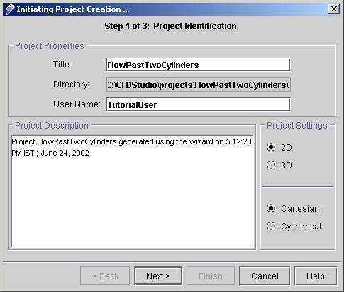
  4. Visualize/Postprocess Only. For our Project setup we need to select "Start a New Project- ANSWER Project Setup Wizard" >>Go to start the project. A new dialog window appears to specify the project identification having options like project title, User name and the options for the grid type. Enter the required information as shown in Fig. 1.2.

Fig - 1.2: Project Identification dialog box

3) In the Title field, type "FlowPastTwoCylinder". This is a very important step. The project title is used as the folder and file names for all project files. For instance:

Commands (input) file: FlowPastTwoCylinder.inp
Output file: FlowPastTwoCylinder.out
Archive (save) file: FlowPastTwoCylinder.sav
Diagnostics file: FlowPastTwoCylinder.dgn

... and so on. All these files will be created on the server and placed within a folder also named FlowPastTwoCylinder.

Hence it is very important that the Project Name is one-word, and not too long. It is a good practice to CapitalizeTheFirstLetterOfEachWord (as opposed to capitalizethefirstletterofeachword) for ease of read.

4) The default Directory name will be provided to the Project based upon earlier selection. However user can specify a new directory location by following Options - Project Manager. (Make sure you cancel the Wizard before to use Options menu).

5) In the User Name field, type your name. For specifying the grid type, select either 2D or 3D based upon your Project requirements. Here in this case we will choose 2D Cartesian.

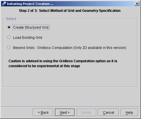
6) Click "Next >" to reach "Grid and Geometry Specification" page. Choose a option to generate a new grid or to load a existing grid as shown in fig.1.3. For present problem choose "Create Existing Grid".

Fig - 1.3: Screen for Grid and Geometry Specification

7) Click "Next >" to reach "Create Structured Grid" dialog box.

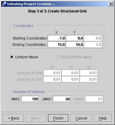
8) We will generate a rectangular geometry with left bottom corner at coordinates (-7,0) and right-top corner at coordinates (15,10). We will use 100 vertices (IMAX) in x direction, and 60 vertices (JMAX) in y direction, so enter these values accordingly. Note that the text field for KMAX is grayed out for a 2D case. Fig.1.4 shows the dialog box filled with corresponding values.

Fig - 1.4: Preprocessor dialog box

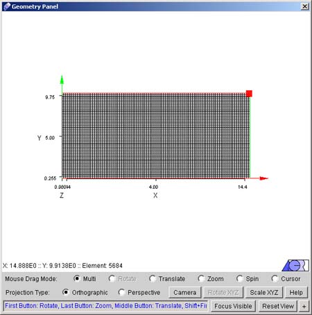
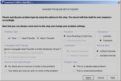
9) Click "Finish" button. A new geometry is created in the geometry panel and a window appears for "ANSWER PROBLEM SETUP WIZARD". (See Fig.1.5 and 1.6)

Fig - 1.5: Geometry panel after creating the grid

The small red square on the grid is the Cursor. We can choose various options like Rotate, Zoom, Spin etc. from Mouse Drag mode on Geometry panel. Try to play with these options to get feel of the geometry.

Fig - 1.6: Window for Answer Problem Setup Wizard.

1 2 3 4 5 6 7


Back to CFDStudio/ANSWER Tutorials Page


Related Links:

ANSWER Applications
ANSWER Examples
ANSWER Express
ANSWER Publications
ANSWER Users
ANSWER Price List
Request CFDStudio/ANSWER Demo
CFDStudio/ANSWER Tutorials
ANSWER Manual


HOME | SOFTWARE | DOWNLOADS | APPLICATIONS | CONSULTING | STORE | COMPANY

© 2015 ACRi